As a new advanced dynamic harmonic mitigation technology, the active power filter has advanced technology based, which has been widely used in many fields.When commissioning the active power filter, it should be noted that the active power filter system should be connected with the circuit breaker and the CT current transformer.
But how to calculate the active power filter size for a real project? CoEpower has summarized some reference for you based on our decades years’ experience in this power quality solution field.
1.Design procedure
Overall, for new projects, Users can configure the APF capacity according to the following reference.
Firstly understand the distribution system of the drawing, estimate the harmonic current value, select the capacity of APF according to the harmonic current value; then select the corresponding APF model according to this capacity; then determine the installation location and installation method according to the prduct size; and finally reflect the product model on the drawing to complete the type selection process.Details can be done following the following procedures:
(1)Capacity select
(2)Model Select
(3)Dimension confirm
(4)Drawing on the schemaic
1.1 Capacity Select
This step is mainly to determine the installation capacity of APF. During the design, the electrical designer first estimates the harmonic current effective value of the power distribution system first.
The detailed real process of the capacity design stage is described as follows:
The calculation of harmonic current value is involved with many factors. For the calculation of harmonic current value, we suggest a special power quality analysis instrument.However, for new projects, only in the design stage, electrical designers can not obtain enough electrical equipment harmonic data,take this into consideration,we configure APF for this kind new project based on the test and experience summary of many industries, the experience formula for electrical designers in the design selection as reference.Using the following formula meets the design requirements to select the APF according to the calculated harmonic current.
1.2 Centralized governance
Formula -1:

Noted:This formula is Suitable for centralized treatment on the secondary side of the transformer.
Formula data explanation:
S : Transformer capacity;
U : Transformer secondary side rated voltage;
K : Load Rtaio;
IHR: Harmonic Current;
THDi : Total Harmonic Current Distortion ratio
The taken value range:
1)K Represents the load rate of the transformer,The taken value range of transformer design is 0.6-0.85。
2)THDI Is the only variable value in the formula above formula,Its range of value depends on different industries and industry loads.
1.3 Local governance
The above formula is determined for the centralized treatment of the harmonic on the secondary side of the transformer. Here, it is recommended to treat the harmonic at the secondary side of the transformer, it can also be treated locally at the input end of the load.Calculculation can be performed using formula 2 below.

In these formula, IN represents the rated current of APF.The above formula only considers the load running at full load (K=1).Actual operational K aavalues should be considered in the design, as in Formula 3.

1.4 Partial governance
If we know the know capacity / power, then the harmonic current value can be calculated.For example, the total load capacity (power) below a branch A is P (and here can be a single device or multiple devices), then the harmonic current can be calculated by Formula 4.
Formula-4:

Where, the U N represents the rated voltage (line voltage) of the device.The P represents the total capacity (power).The K represents the load rate.
Formula explanation:
(1) THDi select
As we can see from the analysis above, that THDi is the main variable value need to be confirmed, and then this value can be determined based on the harmonic analysis in Chapter.
(2) Quick model select
Quickly selected can according to formula _ 1-4 of the industry summary of various industry harmonics ,and then in Table 3.9.
2 .Product select:
Refer to the harmonic current value calculated in Section 1.1 to determines the capacity to be installed according to the model of APF.The APF installation capacity can be determined according to Formula 5,The coefficient is to maintain the capacity reductant
Formula-5:

Among these, the IA presents the installation capacity of the APF.The IHR represents the harmonic current value.
See the product selection section in the product introduction in Chapter 4 for detailed product selection.Among these, the IA presents the installation capacity of the APF.The IHR represents the harmonic current value.
2.1 High-altitude applications
According to the mechanical industry standard of JB/T7573-94, we conclude the following main influence rules of plateau climate conditions are as follows: plateau has harsh natural climate conditions, characterized by:
A,Low air pressure or low air density;
B,The air temperature is low and the temperature changes greatly;
C, The absolute air humidity is low;
D, The solar radiation illumination is high;
E, Less precipitation;
F, More windy days;
G,Soil temperature is low, and the freezing period is long.
These characteristics have the following main effects on the performance of electrical products:
1)Effect on the strength of the insulating medium
The decrease in the air pressure or air density causes a decrease in the external insulation strength.Within an altitude of 5000m, every rise of 1000m,That is, the average air pressure decreases by 7.7 to 10.5kPa,The external insulation strength is reduced by 8%~13%.The impact of the low air pressure on the equipment is mainly manifested in the decline of the external insulation performance to the electrical equipment: when the altitude rises, the air density decreases, the heat dissipation conditions deteriorate, and the temperature rise of the high pressure components increase during operation.The rated current can be maintained the same, but the air insulation strength is weakened, which makes the external insulation strength of the components also weakened, easy to occur such as insulation breakdown or flash collaterals destructive discharge accidents.
2)Effect on medium cooling effect,product temperature rise
A decrease in air pressure or air density causes a reduced effect of air medium cooling.For electrical products with natural convection, forced ventilation or air radiator as the main heat dissipation mode, the temperature rise increases due to the decrease in heat dissipation capability.Within an altitude of 5000m,every rise of 1000m,That is, the average air pressure decreases by 7.7 to 10.5kPa,the tempeature will rise by 3%-10%.
a、The temperature rise rate of static electrical appliances increases with elevation, every rise of 100m is generally within 0.4K, but for high heating appliances, such as electric furnace, resistors, welding machine, the temperature increase rate with elevation reaches more than 2 K per 100m.
b、 The temperature rise of power transformer is related to the cooling mode. The increase rate per 100m is: oil immersion, 0.4% of rated temperature rise; dry self-cooling, 0.5% of rated temperature rise; oil immersion forced air cooling, 0.6% of rated temperature rise; dry forced air cooling, 1.0% of rated temperature rise;
c、 The temperature rise of the motor with elevation is the rated temperature rises of 1% per 100m.
Summary: For the application of active power filter in high altitude area above 1000m,every rise of 100m, the APF capacity should be reduced by 1% .
2.2 Dimension confirmation
After capacity determination and product selection confirmed, the installation location and installation method can be selected according to the selected APF to meet the requirements of the site.Recommended rack / vertical cabinet mounting methods for large mounting capacity.
2.3 Drawing
After the capacity and size are determined, APF design can select the distribution system diagram.During APF installation, the following accessories are required:
Current transformer (CT), circuit breaker.The CT and circuit breakers need to be shown on the drawings.See Chapter 4 for product selection for the host size and accessories.
2.4 Design procedure reference
Capacity design and product selection:
Selection type is distribution system of a hospital: rated capacity of transformer is 1000kVA, transformer ratio is 10 / 0.4 kV.The K value is 0.8 and the THDi value is 20% (according to the harmonic analysis in Chapter 3) ,and is available according to Formula 1 (the design method in Chapter 1):

Harmonic current is 226A,we calculate according to this formula and also give some reductant capacity,hence ,we selected APF 4L/250-0.4(APF Capacity is 250A,rack mounted installation method)
Dimension confirmation:Harmonic current is 226A,we calculate according to this formula and also give some reductant capacity,hence ,we selected APF 4L/250-0.4(APF Capacity is 250A,rack mounted installation method)。
APF Adopt a modular design.A total capacity of 250A, is composed of two modules with a parallel capacity of 100A, and a capacity of 50A.The parallel machine system needs to be equipped with an active filter cabinet, the configuration cabinet size is 800(W)×800(D)×2000(H)mm 。
To meet the site requirements, we can also choose the same type of distribution cabinet as the low voltage distribution sets (but must meet the width ≥ 600mm).Unified color standard and appropriate adjust cabinet size according to user requirements to make the overall distribution unified.For example, in this case, select the GCS model power distribution cabinet with 800 (W) × 800 (D) × 2200 (H) mm.
Product selection

Instructions:Figure 2.2 APF 3P4L Product
1、 APF can be applied in three phase four wire system(such as model select 2.2),select based on real power distribution system.
2、 For three-phase four wire products, need three units CT, The CTS shall be installed on A, B, C three phase, as in this example; we adopt CT with 5A at secondary side,XXXX/5.
3、 CT access point:If there is capacitor banks in presence of the system,the CT access point should be connected between capacitor banks and the load,in other words,the CT should be connected downstream of the capacitor banks.Just like the 2000A/5A CT Access point in this example.
4、 The CT on the APF input side in this case is not the principle of the APF system, it’s only to ensure the consistent cabinet type.
5、 Installation location of CT and APF output cables:
There is no big difference in the the individual signle wall mounted APF module system.However, In the parallel system, the installation point of the CT is closer to the load side relative to the access point of the power cable (i. e., the connection point of the circuit breaker), called the CT load side connection method.It’is recommended to adopt the CT load side connection method for both single and parallel systems.
2.5 Instructions for selection
1、 The APF, circuit breaker and CT constitute the whole APF system, so these three must be well reflected in the type selection.
2、 For APF/CT/Circuit Breaker selection of the above three, see product selection in Chapter 4.
3、 If have any doubt about selection,please contact us for explanation.
3. Harmonic Analysis
In an ideal clean power system, both voltage and current are pure sinine waves.In fact, a non-sinusoidal current forms when the current flows through the load where the power supply is not linear to the added voltage.This type of nonlinear load is collectively known as harmonic source loads.
Fourier analysis of the periodic nonsinusoidal current yields a superposition of a series of sine wave currents at different frequencies, except for the power of the base wave frequency, whose full multiple of the base wave frequency is called the harmonic.
The order of harmonics is the ratio of harmonic frequency to base frequency (n=fn/f1), such as 150Hz is called 3 harmonics and 250Hz is called 5 harmonics
Harmonic current causes problems both in the power system and in the device.The following problems are mainly caused by harmonic: high voltage distortion; over zero noise; neutral line overload; overheating of transformer and induction motor; circuit breaker error; correct overload damage of power factor capacitor; and skin collection effect.
3.1 The office building
3.1.1 Industry introduction
In recent years, modern office buildings are developing rapidly into building automation, the number and proportion of non-linear load power equipment in the electricity equipment are rapidly increasing, and the power quality pollution to the urban power grid is increasingly serious.Among these large number of automation equipment, common nonlinear loads are: video display equipment (CRT and LCD display equipment), computer equipment, air conditioning, all kinds of energy saving lighting equipment (fluorescent lights, various high pressure gas discharge lights, dimlights, etc.), office electrical equipment (printers, copiers, scanner, projector, etc.), speed control drive (frequency conversion pump, air conditioning compressor, large elevator).These will all become the harmonic distortion perturbation source of the low-voltage power supply system.
Office Building power distributionsystem has many single-phase equipment and high nonlinear load ratio.The main power quality problems include:
1) A large number of zero sequence third harmonic current injected into the power grid, so that the third harmonic voltage of the low-voltage power supply bus seriously exceeds the national standard limit, and affects the safe and normal operation of the low-voltage electrical equipment, especially the harmonic-sensitive equipment.
2) The current on the neutral line is too high (zero sequence current will be superimposed on the neutral line, mainly third harmonic current), resulting in neutral line heating and increased line damage, while the wire used in the design is thin, so it is prone to cause fire hazard due to high temperature.
APF targets at the characteristics of zero sequence harmonics pooling on the neutral line, and the filtering capacity of the neutral line reaches three times of the phase line, effectively reducing the neutral line current and improving safety reliabilit
3.2 Medical institutions
3.2.1 Industry introduction
Medical technology equipment is the key harmonic source: mainly NMR equipment and accelerators.The harmonic spectrum of NMR equipment is very complex. The typical spectrum is concentrated in 3,5,7 and 9 orders, and the harmonic spectrum range is from 3 ~ to 43 orders.The typical spectrum of Accelerator is concentrated in 3,5,7,9,11,13 orders, the spectrum is wide, and the harmonic spectrum range is 3~49 orders.
We conducted an equipment test in a hospital,and fund from the test data analysis that the accelerator, X optical machine, gastrointestinal machine and other equipment produced THDi in about 50%~60%, CT(computed tomography), magnetic resonance, DSA(digital subtraction angiography machine) in about 30%; electronic detection equipment, operating room, gamma knife, etc. between 10%~15%, frequency conversion equipment in about 35%, etc.
The harmonic current in the hospital power distribution system has the following characteristics:
1 ) The spectrum of the harmonic current produced by the harmonic sources is very wide.
2 ) The harmonic current distortion rate is high as well as the natural power factor of the device.
3 ) There are many electronic equipment, medical technology and equipment in the hospital, and these equipment are very sensitive to harmonics.
3.3 Data Center
3.3.1 Industry introduction
UPS is an indispensable part of the equipment used to ensure the high reliability of communication and electricity consumption.In today’s large and medium-sized UPS production, more 6-pulse silicon controllable silicon type rectifier UPS design scheme is used.UPS can provide high quality power supply with high voltage stabilization and high accuracy, stable frequency and small waveform distortion.On the one hand, the use of DC switch power supply in UPS and communication room solves the power quality problems of ordinary users well, such as voltage instability and power supply continuity. However, because the input side of UPS and DC switch power supply adopts rectification circuit, both have become the main nonlinear load in the power grid.
The main power quality problems as follows:
1) Produces a large amount of harmonic current, which not only pollutes the power grid but also transfer the harmonic to the IT equipment, causing serious interference and even harm to the communication system.Harmonics are very sensitive to these systems and may occur such as computer system paralysis or death, stagnation, distortion, and system control distortion, which will cause great losses.And it should be specifically pointed out that the harmonic interference hides the disaster of the entire system collapse that will happen at any time.
2) harmonics will cause power loss of the standby generator, reduce the output power of motor operation at full load, and affect the power supply safety.
3.3.2 Harmonic analysis
The UPS application, usually uses the “N+ 1” redundancy.Then the total harmonic distortion rate of the input side current THDi (leading to UPS is often different, some cases THDi can exceed 50%, pollution is quite serious.The following table shows the harmonic measurement results on the UPS input side of a company.
3.4 Public facilities
3.4.1 Industry introduction
Public facilities include large performing arts centers, studios, exhibition centers, stadiums, etc.The above occasions have high requirements for light and shadow and sound. The stage dimming is mainly a silicon controlled light dimming system. The basic principle is to adjust the output voltage range of both ends of the light by changing the control angle size of the silicon controllable light, so as to realize the light brightness adjustment.The basic principle of phase control rectification determines that the current distortion is serious during this load operation, especially with light load operation, which brings harmonic pollution to the power distribution system.In addition, the UPS and the central air conditioning system are also common harmonic sources.After using APF filter for harmonic elimination, it can ensure the normal operation of electric energy quality sensitive equipment such as dimming system and sound system, avoid false action of the switch cabinet, reduce the harmonic crowding out the transformer capacity, and eliminate the serious safety hidden danger of overheating of the neutral line caused by the superposition of 3 harmonic waves in the neutral line.
3.5 Banking Finance
3.5.1 Industry introduction
Banking and securities system adopts high quality safe and stable automation management, and adopts huge office automation, equipment automation system and communication automation system.The large amount of UPS and switching power in banking and securities systems rooms produced a large number of harmonics.In addition, the large number of electrical equipment used in the office system and the frequency converter-controlled elevators and air conditioning also produce considerable harmonics.Harmonic is very sensitive to the automatic control of banking and securities system, which may cause paralysis of computer system, system control abnormal, and banking system network operation, such as failure of data processing center, will affect the operation of the whole networked system, which will cause immeasurable losses.
3.6 Manufacturing industry
3.6.1 Industry introduction
There are many kinds of large production and manufacturing industries, typical of cigarette factories, automobile manufacturers and so on.There are many kinds of load in cigarette factory, including: 1 production equipment: shreds production line, winding production line, packing production line and other production equipment; 2 power center load: including fan, water pump, etc.Most of these equipment use frequency conversion drive equipment, in addition to some use of DC speed adjustment.Both the former and the latter, the rectifying circuit is adopted in its electrical design, bringing serious harmonic pollution to the system.The influence of harmonic on automatic production equipment cannot be ignored, will affect its safety operation, reduce the efficiency of the motor; and will cause serious waste of electric energy.
The main hazards caused are as follows:
1) harmonics make the components in the public grid produce additional harmonic loss, reduce the use efficiency of power generation, power transmission and electrical equipment, and a large number of three harmonics flow through the middle line to overheat or even fire.
2) harmonics affect the normal operation of various electrical equipment.In addition to additional loss, the influence of harmonic on the motor will also produce mechanical vibration, noise and overvoltage, which makes the transformer seriously overheated.Harmonics make capacitors, cables and other equipment overheating, insulation aging, life shortening and damage; for compensation power capacitors and series resistance, high harmonic current through the capacitor circuit, may cause series resonance or parallel resonance phenomenon, overheating damage, vibration, flicker accidents; according to statistics, the capacitor accounts for about 40% of electrical equipment damaged due to harmonic accounted for about 30%, other electrical equipment damaged by harmonic is also greatly related to the capacitor.
3) harmonics is prone to cause parallel or series resonances between the grid and the compensation capacitors.Make the harmonic current magnified several times or even dozens of times, causing excessive current, causing damage to the capacitor, the connected reactor and resistors, and even causing serious accidents.
4) harmonics cause misactions of relay protection and automatic devices (e. g. relay protection, fuses, etc.) and also cause inaccurate measurement of electrical measuring instruments.
The 5) harmonic will interfere with the adjacent communication system through electromagnetic induction and conduction coupling, which induces noise and reduces the communication quality; which causes information loss and the communication system cannot work normally.
3.7 Water treatment plant
3.7.1 Industry introduction
The sewage treatment plant adopts a large number of power electronic equipment, such as UPS, frequency converter, soft starter, computer equipment, etc.Power electronic devices are a non-linear load, and they absorb energy from the system by not continuous sine waves, but take current from the system by pulse interruption, resulting in a distortion of the input side current.These power electronic equipment are the harmonic source of sewage treatment plant, the operating conditions of these equipment often change, such as a large number of frequency converter used in the submersible pump and blower group, its harmonic component and proportion change greatly, and have a great impact on power supply and consumption.In the actual process, because the blower room is a non-linear load center, many blowers use the frequency converter centrally, it is likely to produce a large number of harmonics, which can cause abnormal motor heating, unstable state during continuous operation and large motor vibration, so that the blower cannot operate normally and reduce the sewage treatment effect, the sewage treatment process is serious, not only causes direct economic losses, but also leads to water environment pollution.Therefore, sewage treatment plant harmonic treatment to reduce harmonic pollution.
3.8 Other industry
In addition to the above industries, there are petrochemical, mineral development, steel plants, non-ferrous metal processing, glass factory, port, urban transportation and other occasions will be contaminated by harmonic distortion.Among these industries, the common harmonic sources are hot mill, cold mill, welding machine, Intermediate Frequency furnace, arc furnace, DC motor, frequency converter, electrolytic tank, etc.The characteristics of this kind of enterprises is that the load current is large, and the current changes rapidly, strong impact, and the voltage level is also different, it is still difficult to carry out general statistics.
Therefore, if the harmonic governance is to be carried out on the above industries, we must understand the specific load of the actual power distribution system, and the power of this kind of load is large, it is recommended to adopt local governance or partial governance.
For designers to conduct harmonic governance on such industries or the unmentioned industries, please contact CoEpower for more explanation.
4 Product select
4.1 APF select
1,The capacity configuration of the APF is only related to the harmonic current value of the installation location.The APF capacity is only defined by the output current of the APF, not by the power consumed by conventional other electrical equipment, which must be clear.
2,The harmonic current of the installation position can be calculated from the formula contained in Chapter, select by the capacity of APF according to this value,.
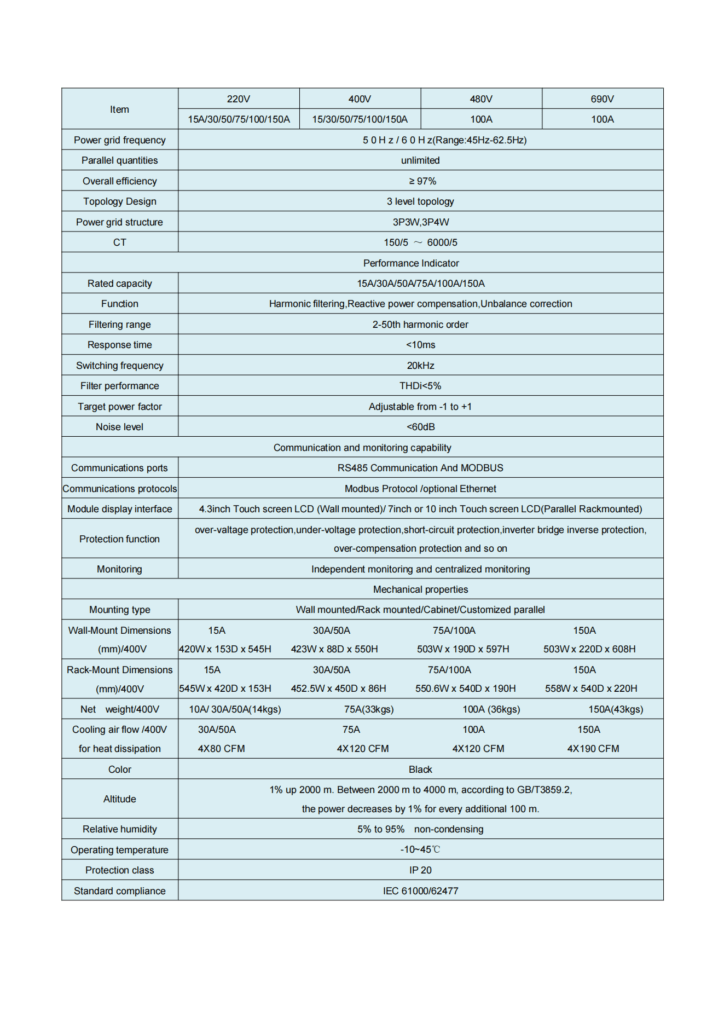
3, The APF 380/400V class has a single-machine capacity of 30A,50A,75A,100A,150A.If you want to choose a large capacity, it can be expanded in parallel through the above modules. The maximum number of recommended cabinet configuration is no more than 6 modules. Other capacity levels can be contacted with the Company.
Model explanation
APF Signle module:
Suggest model select
For 380 / 400V voltage rating, three-phase four-wire systems, we recommend APF using the following installation capacity.At present, CoEpower APF adopts three phase four line system, other line system rquirement please contact our company.
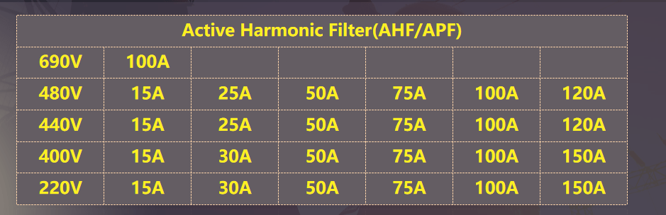
Table 4.2 APF technical parameters
4.2 Accessories selection
CT selection
1. The rated working voltage of the CT shall comply with the sytem rated voltage.
2. The CT primary current ≥ rated system load current, It’s generally selected by 1.5~2 times of the system.The secondary side current is 5A, and the CT ratio is XXXX / 5A.
3. Select the appropriate accurate class CT according to the requirements of electrical measurement and relay protection.Generally, 0.5 accuracy class CT can meet the requirements. If used for accurate measurement, we suggest 0.2 accuracy class.
4. We suggest split core CT,please check the following table for details.
5. Current we suggest to use CT:150/5一6000/5.
Circuit breaker select:
1.The rated operating voltage of the circuit breaker shall comply with the system rated voltage.
2. Rated current: Generally selected rated current is 1.25~1.5 times of the APF output current, or choose a higher grade.
3. Limit separation ability, choose the same grade as the electrical equipment of the same level.
Cabinet select:
1. Considering that the design selection is mainly for new projects, in order to ensure coordination and beauty with the distribution environment, CoEpower APF recommends the rack installation method and choose to be installed inside the cabinet.
2. When the CoEpower APF is rack-mounted, the APF module is placed in the cabinet.
3. The cabinet adopts bottom incoming and bottom outgoing ; front and rear doors, front operation and rear maintenance.
4. The cabinet is equipped with perfect and reliable grounding system and protection circuit, which can meet the requirements of the power distribution system, ensure the reliability of power supply, and also ensure the safety of equipment and system.
5. The cabinet size is 800(W)×800(D)×2000/2200(H)mm,The appropriate cabinet height can be selected according to the actual number of parallel modules.
6. CoEpower APF cabinet can select the same type cabinet as the power distribution cabinet(such as GCK, GCS, MNS, GGD) in parallel, or the unified color standard and the cabinet size can be appropriately adjusted according to the requirements of the user, so that the power distribution cabinets can be unified.
7. CoEpower APF also can be placed in the original distribution cabinet, only if the size and heat dissipation requirements are available for APF.
8. It must be clearly noted that If the APF module is installed inside the cabinet ,user must ensure convenient installation and maintenance, especially good ventilation and heat dissipation.