As the upgrade and development of photovoltaic technology, more and more users choose factory distributed photovoltaic power generation, make the best use of the factory roof space to install photovoltaic components, on-site power generation for production use, adopting the self-used first and then the surplus parts access to the grid, when the power generation meet their required electricity capacity, the surplus parts will access into grid photovoltaic power generation system, in order to get profit.
Use the strategy of self-generated surplus to grid access:
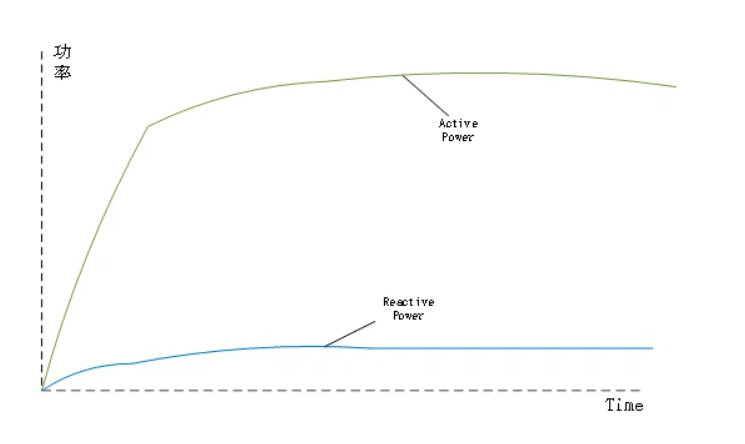
1. When a distributed PV power station generates power, the initial power factor of the pv system is 1 and no reactive power is included
2. The load power consumption machine must need reactive power support when they are on working , it must be supported with or without power
Hence, the active power of the system from the grid decreases, the reactive power of the system is still all drawn from the grid. As a result, the active power on the grid side of the system approaches 0, while the reactive power remains unchanged:
The power factor of the power system will decrease while the PV power generation system is changing , which will lead to the power factor on the metering meters not reaching the standard, resulting in the much penalty.
It should be noted that the required power in the system is not constant, there will be fluctuations;The power generation of distributed PV system is not constant either;This leads to a severe frequently fluctuation of the active power provided by the grid , under this situation ,the reactive power compensation device must response in very short time with stepless adjustment compensation ability of the reactive power compensation cabinet in the system.
1. When the distributed PHOTOVOLTAIC power generation system is not in use
When the distributed PHOTOVOLTAIC power generation system is not in use,The active power required for all the load equipment in the system is provided by the power grid, and the reactive power required for the load equipment is mostly compensated by the reactive compensation cabinet in the system, while the power grid provides little reactive power.
Then at the metering point, the power factor of the equipment is:
The total power of the system electric load stay the same, and the compensation status of the capacitor cabinet is good
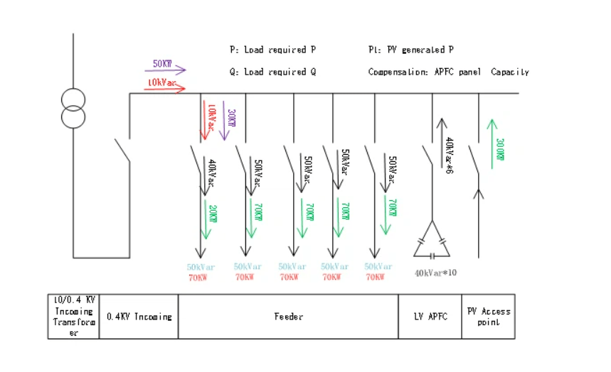
Assuming that:P=350KW Q=250kVar Compensation=40kVar*10
When the equipment is running, the power factor of the electric meters in incoming cabinet is:

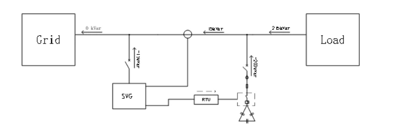
2.Distributed photovoltaic power generation system input, photovoltaic power generation < load required power
When the distributed PV power system is put into operation, the PV generated power does not meet the active power demand of all load equipment on site.
The active power required for the load equipment is composed of (distributed photovoltaic power system power supply + grid power supply). The reactive power required for the load equipment is compensated by the reactive compensation cabinet in the system, while the power grid provides part of the reactive power.
At this time, the power grid provides the power to the user as (partial active power + partial reactive power), then at the metering point, the power factor is:
The total power of the system power load remains unchanged, and the capacitor cabinet is in good compensation condition
P=350KW P1=300KW Q=250kVar APFC Compensation =40kVar*10
When the load equipment is running, the power factor on the metering meters of inlet cabinet is:

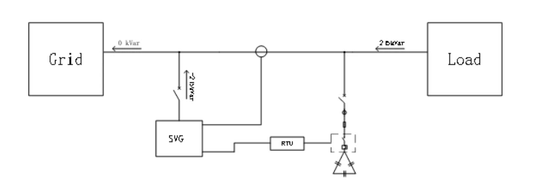
3.Distributed photovoltaic power generation system input, photovoltaic power generation system power = load required power

Distributed photovoltaic power generation system is put into operation for active power demand of all load equipment of photovoltaic power generation system .
The active power of all the load equipment required in the system is provided by the photovoltaic power generation system, and the power grid only provides the reactive power to the load.
The reactive compensation cabinet in the system provides most of the reactive demand of load equipment, when the power supply to users is only part reactive power, at the metering point, the equipment power factor is:
The total power of the system power load remains unchanged, and the capacitor cabinet is in good compensation condition
P=350KW P1=350KW Q=250kVar Compensation =40kVar*10
When the equipment is running, the active power provided by the municipal power is 0, and after the reactive power is compensated by the compensation cabinet, the reactive power supplied from grid is 10kVar,
At this time, the grid power did not provide active power, only provide reactive power, the power factor is immeasurable.

It should be noted that because the power grid side does not flow into any active power at this time, the power grid side power factor cannot be calculated at this time, so the reactive compensation cabinet in the system is prone to fail and cannot be put into compensation.
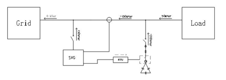
4.Distributed photovoltaic power generation system input, photovoltaic power generation system power> load required power

In this case, the total power of the system load is unchanged, and the capacitor banks cabinet is in good compensation condition
P=350KW P1=400KW Q=250kVar APFC Compensation=40kVar*10
When the equipment is running, the photovoltaic power generation system reverse active power 50KW to the grid power incoming cabinet,the load equiment takes reactive power provided from the grid, the reactive power supplied from grid is 10kvar after compensated by capacitor banks.

Since the active power is reverse at this time, the power factor is PF= -0.98
It should be noted that because the active current is inverted, the reactive compensation cabinet in the system may not operate normally.
The traditional reactive power compensation cabinet adopts the step compensation capacitors compensation (40kVar*10), the compensation mode is the step input, and the minimum compensation step capacity is a single capacitor.
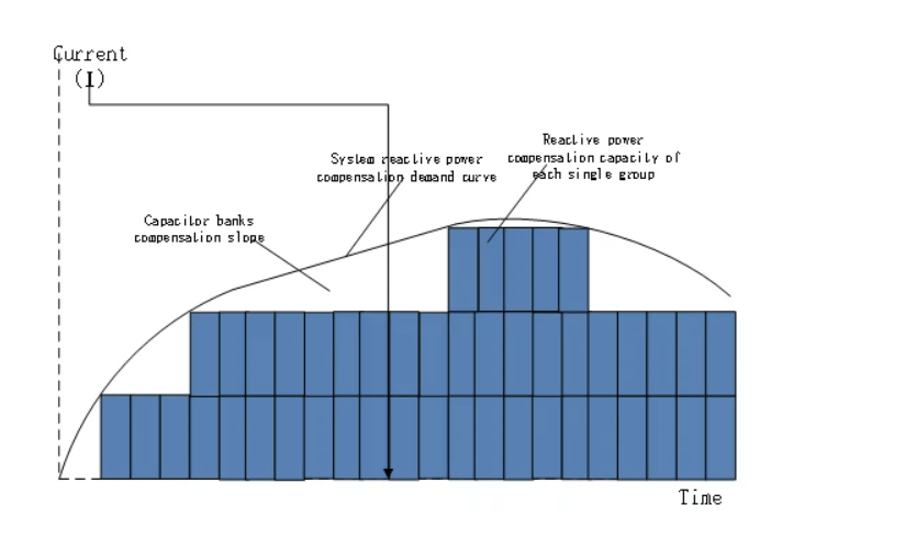
Mode of the reactive power compensation capacitor cabinet
Step compensation is inevitably unable to fully meet the compensation of the system demand, with the change of the reactive power of the system, there will be some compensation gap.
In the power grid side incoming cabinet, the greater the ratio between the active power and the reactive power,the better the system power factor can reach.
However, due to the compensation gap of the traditional reactive compensation capacitor banks, there is actually a minimum compensation accuracy. When the distributed photovoltaic power generation system is put into use, the active power provided by the grid incoming side decreases, the closer to the minimum compensation accuracy of the reactive compensation capacitor banks, and the worse the compensation effect of the reactive compensation cabinet

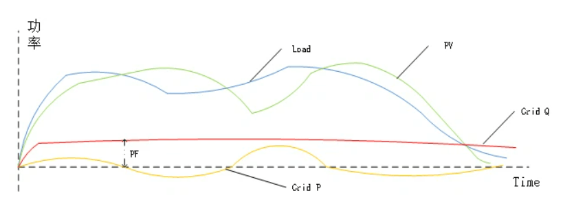
The required power of load equipment remains unchanged. With the gradual rise of power of distributed photovoltaic power generation system, the active power of the power grid side incoming cabinet will gradually decrease, and even the distributed photovoltaic power generation system returns active power to the power grid. Therefore, PF1> PF2> PF3> PF4 at different stages is getting smaller and smaller
In fact, the user’s application field electricity situation is more complex, composed of the above 4 situation, which may also change immediately. Due to the load power fluctuation is big,the distributed photovoltaic power generation system also fluctuates

The two situation superposition, which leads to dromatic and frequent fluctuation of the active power from the power grid inlet cabinet. On this basis, if there is a compensation gap in the traditional reactive compensation cabinet, it cannot meet the demand of reactive compensation in the system, either the power factor of the system power grid.
Finally,the frequent fluctuation of active power in the system, leads to fluctuated power factor, the reactive compensation cabinet need to react in a very short time will seriously affect the performance of the reactive compensation cabinet, this will resulting in compensation capacity decay, will lead to the failure of the reactive compensation cabinet and can’t work normally.
The reason for the above problems lies in the frequent changes of the active power supplied by the grid power; and the step compensation mode of the traditional reactive power compensation cabinet.
The traditional compensation method and control logic of the reactive power compensation cabinet cannot meet the reactive power compensation demand of the users with distributed photovoltaic power generation access.
Reactive power compensation solution for distributed photovoltaic power system
This solution is aimed to improve the power factor on the grid side power metering meters to avoid penalty.
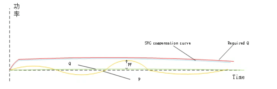
After the distributed photovoltaic power generation system is connected, the active power of the grid incoming cabinet fluctuates frequently and complex, and the reactive power of the load equipment is compensated by the reactive compensation cabinet, there is still a certain compensation gap, which also needs to be provided by the power grid
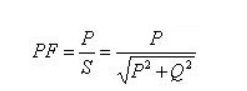
Power factor
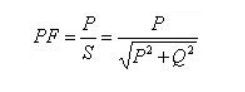
Hence the smaller the reactive power Q, the greater the system PF, when the Q=0 the PF is

In this case, we use a hybrid compensation configuration of our CoEpo SVG static var generator (SVG) + capacitor banks. Use our CoEpo RTU intelligent hybrid controller to switch this hybrid reactive power compensation, this configuration gives a higher compensation accuracy and faster response in real-time tracking.

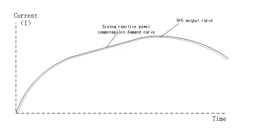
The total reactive compensation demand is calculated by SVG , RTU intelligent hybrid controller controls the capacitor bank input.
When the system reactive compensation demand is detected, SVG will make a fast response and gives first reactive power compensation supports.
At the same time, the RTU intelligent hybrid controller controls the capacitor input. When the capacitor bank is input, the SVG compensation output can be reduced, then SVG will compensate the reactive power slop from the capacitor banks step shift.
Therefore,this will not only maintain the highest power factor, but also reduce the switch frequency of capacitor bank, and the SVG equipment will also avoid a not have a continuous full load working condition.
When the reactive compensation demand of the load decreases, the capacitor bank presents an overcompensation. Under this situaion SVG will outputs the reverse reactive power to offset.
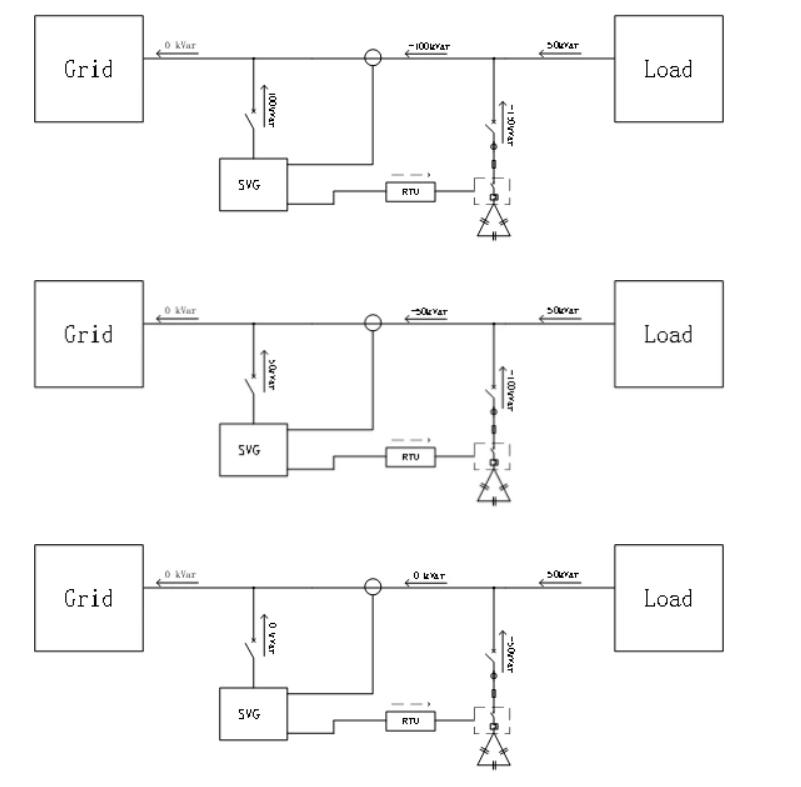
The capacitor bank is switched on/off by RTU hybrid controller,the SVG corresponding output reverse reactive power to offset. Thus will keep the power factor at an ideal level.
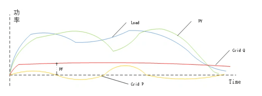
After a hybrid compensation by SVG+ capacitor bank, the reactive power provided by the grid to the user is infinitely approaching 0,thus the power factor PF remains at a higher level regardless how much active power supplied by the grid to the user
This hybrid reactive power compensation mode can not only achieves comprehensive compensation, but also reduce cost.The compensation range from 1~ (-1) gives real-time adjustment to ensure the best compensation effect.
SVG sizing reference

The detailed compensation capacity sizing shall be subject to the site measurement
1. Firstly conduct a measuring for the project site;
2. Sizing based on the measurement analysis and the exsiting reactive power compensation cabinet
3. Conduct the installation design according to the site conditions
4. Installed SVG and renovate the original reactive compensation cabinet for unified control
5. Conducts equipment debugging to achieve the best compensation effect
6. Project acceptance
CoEpo SVG static var generator Working Principle

Working Principle
CoEpo SVG collects the current signal in real time through the external current transformer, and the DSP calculates the required reactive current, then, IGBT power converter generates a reverse compensation current with the same phase to offset, thus realizing the function of reactive compensation.
The compensation target power factor value can be set through the user interface, the CoEpo SVG will not overcompensate or undercompensate,the compensation current is smooth, with no surge impact on the load and the grid.
CoEpo SVG Main Feature
CoEpo SVG Main Feature
1) Compensation range: 1~ (-1), real time automatic bidirectional compensation.
2) Responds faster, full response time ≤ 10ms.
3) Modular structure. When any of the modules fails, it does not affect the normal operation of other modules, which ensure the reliability of the device operation, and can easily realize the expansion in the original cabinet by increasing the power module.
4) Compensation capacity:> 95%.
5) The IGBT power conversion module adopts three-level topology.
6) Overcurrent limit: a reliable flow limit control link is adopted. When the reactive current in the system is greater than the capacity of the SVG, the device can compensate to the maximum within its rated capacity,to maintain normal operation, without overload burning and other faults.
7) DSP + FPGA control mode, military-class FPGA chip, dual-core DSP chip, computing capacity is much higher than the traditional DSP chip, and has military-level anti-interference ability.
Reliable lightning strike surge protection device is set at the input terminal of 8) Surge protection design.
9) Control algorithm adopts adaptive frequency domain screening vector compensation algorithm to make better compensation effect and higher mature and stable reliability.