1. Project Overview
This metal processing plant uses a large number of spot welding equipment. The single welding time of such equipment is extremely short, and the load fluctuates violently. At the same time, because most of the equipment uses 380V single-phase power, it causes serious three-phase imbalance and a large number of The generation of reactive power.
Under such working conditions, the switching speed and compensation mode of traditional reactive power compensation capacitors are far from meeting the frequency of system reactive power fluctuations and the requirements for compensating system reactive power. At the same time, due to the frequent switching of capacitors, This causes frequent insufficient discharge of the capacitor itself and accelerates the aging of the capacitor.
2. Distribution System Diagram and Problem Analysis

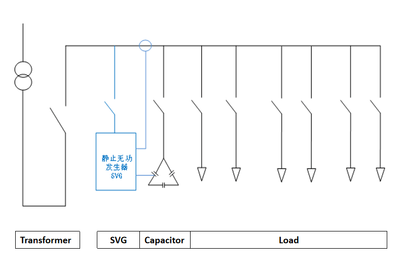
This site is a typical 0.4KV power distribution system structure:
Transformer→Incoming line cabinet→Capacitor cabinet→Load outlet cabinet
Symptoms of the problem initially discovered at the scene:
- The capacitor is damaged, and problems such as capacitor aging and bulging occur on site.
- Reactive power compensation is not up to standard, resulting in a large amount of power regulation fines.
Problem cause analysis:
Since the welding time of spot welding equipment is very short, the reactive power generated by the equipment will fluctuate very violently, with short duration and high peak value; at the same time, since the spot welding equipment is 380V single-phase (A/B, A/C , B/C, etc.), a large number of phase imbalance problems will occur. The original system reactive power compensation equipment uses contactor switching. The switching time is too long and cannot keep up with the reactive power fluctuations of the system, resulting in power factor It cannot be replenished, and at the same time, because the system power factor fluctuates too drastically, the capacitor will be switched on and off repeatedly when the charging and discharging of the capacitor are incomplete, resulting in accelerated aging of the capacitor and the occurrence of bulges and other problems
3. Solution
Precondition 1: SVG responds faster than capacitors
Precondition 2: SVG sampling transformer requires the load side, and capacitor cabinet sampling requires the power side.
Using SVG and capacitor hybrid compensation, both use the same current sampling signal
The equipment installation sequence is: transformer → incoming line cabinet → SVG cabinet → sampling transformer → capacitor cabinet → load
Equipment selection: static var generator (SVG) + traditional capacitor cabinet
Equipment model: CoEpo SVG/150-0.4-D
Governance method: mixed compensation, centralized governance
Installation capacity: 150kVar+400kVar
Installation method: rack type
Installation location: Power distribution room

When the system generates a reactive power compensation requirement of 200kVar, the current sampling transformer samples the corresponding signal and transmits it to the SVG and capacitor cabinet at the same time. The SVG responds faster. The SVG first inputs compensation according to the current signal and outputs compensation of 150kVar. Due to the installation position of the current transformer It is located at the back end of the SVG, so after the SVG signal is output, the transformer sampling signal is still a reactive power compensation requirement of 200kVar, and this signal is passed to the capacitor cabinet

The capacitor cabinet outputs according to the current sampling signal, and the output compensation capacity is 180kVar. Since the transformer is installed in front of the capacitor cabinet, the current sampling signal of the transformer changes, and the measured reactive power compensation requirement becomes 20kVar. The signal is transmitted to SVG, and SVG is based on The current sampling signal changes the compensation output, and the SVG compensation output drops from 150kVar to 20kVar. Since the current signal sampling mode of the capacitor cabinet is for power supply side sampling, the compensation output capacity of the capacitor cabinet remains unchanged.
At this point, the compensation output of the SVG equipment and capacitor equipment is stable, and the system power factor reaches 0.99.
4. Compensation effect
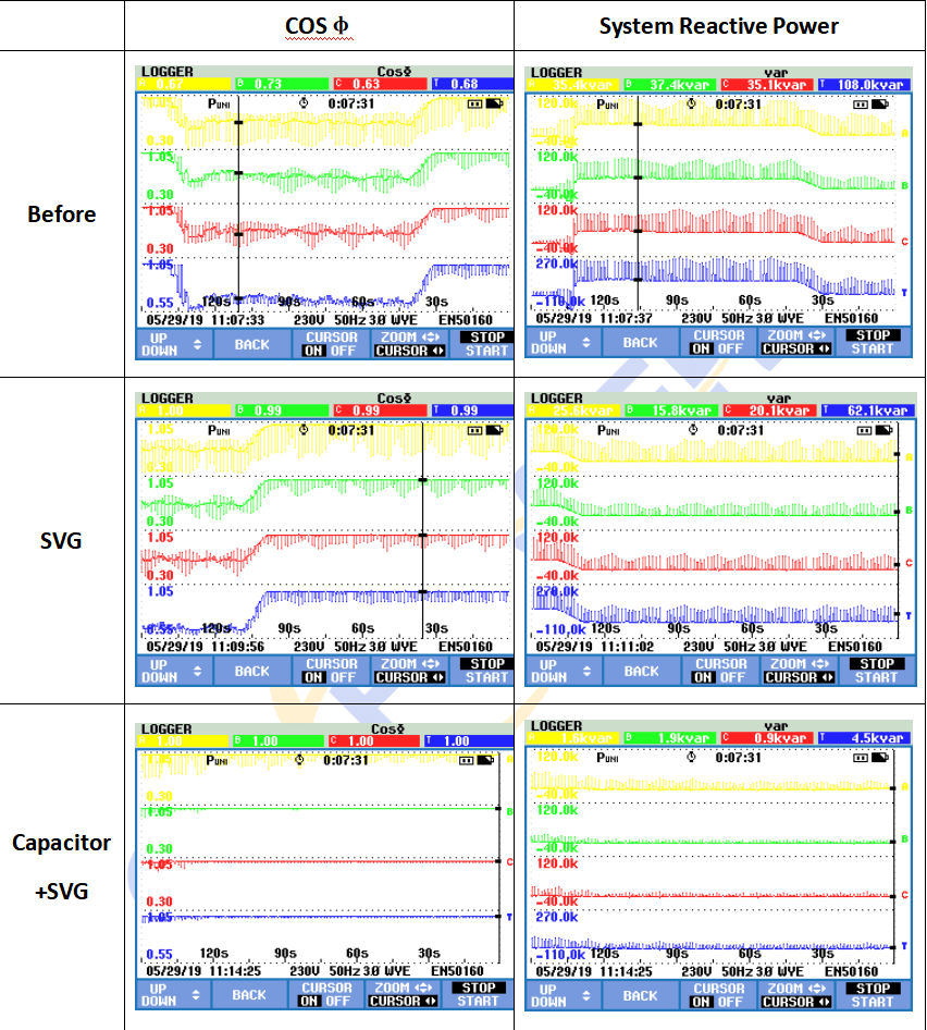
Before reactive power compensation is performed, the system power factor is very low, and there are obvious reactive power fluctuations caused by impact loads.
SVG first compensated, greatly reducing the system’s reactive power and raising the system power factor to 0.99. However, due to SVG capacity limitations, although the total power factor was very high, there were still impactful reactive power fluctuations.
The capacitor is put into compensation and the SVG compensation output capacity is reduced. Using the capacitor position and SVG as an adjustment, the system power factor rises to 1. At the same time, the reactive power fluctuation caused by the impact load is obviously suppressed.