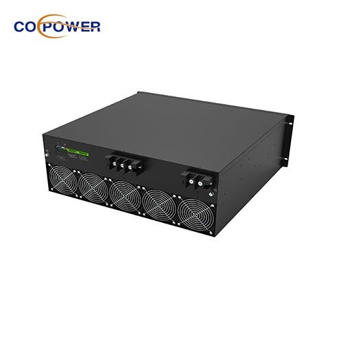


SVG静的VARジェネレーター 力率補正と高調波フィルタリングを目的とした製品です, 3相バランス関数とともに. インバーター技術の恩恵を受けます, SVG Static Var Generator PFCシリーズの補償は段階的です, つまり、SVG出力はシステムの反応電力と一致するものとすることを意味します, 過剰補償や過少補償なし. 単一のモジュール用, SVG容量の範囲は30kvaから100kvaです. Abinetシステム用, 無制限の並行デザインです. 負荷が誘導電流または容量性電流を生成しているとき, 負荷電流ラグを作成するか、電圧をリードします. SVGは位相角の差を検出し、グリッドにリーディング電流または遅延電流を生成します, 変圧器側の電圧の位相角を作る電流の位相角を作る, つまり、基本的な力率は統一です.
 |
 |
| キャビネット容量 | 30-500Kvarキャビネット |
| 定格電圧(v) | 220V/400V/480V/690V |
| 定格頻度 (Hz) | 50Hz/60Hz |
| ネットワーク構成 | 1P2W/3P4W/3p3W |
| CT比 | 100:5〜6000:5 |
| トポロジデザイン | 3 レベル |
| 力率補正 | PF = 0.99 |
| 完全な応答時間 | ≤10ms |
| IGBT周波数 | 20KHZ |
| 通信インターフェイス | RS485, イーサネット |
| 通信プロトコル | modbusプロトコル |
| 保護クラス | IP 20 |
| 証明書 | tuv ce/as/url |
| ノイズレベル | <60DB |
現代の電気システムで, 多くの種類の産業機器, モーターなど, インバーター, および溶接機, 誘導電流または容量性電流を描きます. これにより、電圧が遅れているか、電圧の前にリードします, 非ユニティの力率と電力品質の低下をもたらす.
CoePower Static VARジェネレーターは、この問題を動的かつ正確に解決するように設計されています.
(1). リアルタイム検出
CoePower SVGは、電流と電圧の位相角の差を検出することにより、電気負荷をリアルタイムで継続的に監視します. この位相角の違いは、システムが経験しているかどうかを示します:
-帰納的負荷 (電流ラグ電圧)
-容量性負荷 (電流は電圧をリードします)
(2). 瞬間的な補償
CoePower SVGが位相の不一致を検出したら, 組み込みの高速スイッチング電子コンポーネントを使用しています (例えば。, IGBT) 補償電流を生成します:
-負荷が誘導性がある場合, リーディングを生成します (容量性) 現在.
-負荷が容量性がある場合, 遅れを生成します (帰納的) 現在.
この補償電流は、一般的な結合の時点でグリッドまたはシステムに注入されます.
(3). 統一力率を達成します
CoePower SVGの目標は、変圧器またはシステム入力の電圧波形と電流波形を密接にすることです. 電流と電圧が位相にあるとき, 基本的な力率はほぼに修正されます 1.0, それは意味します:
-電力供給の最大効率
-最小限の反応性電力フロー
-エネルギー損失と機器のストレスの減少
(4). 知的 & 適応操作
固定されたステップに切り替える従来のコンデンサバンクとは異なります, CoePower SVGは滑らかで提供されます, ミリ秒応答時間による段階的な補償. 動的に適応します:
-急速な負荷の変化
-変動する力率
-複雑な高調波が豊富な環境
CoePowerの静的VARジェネレーターは、電流と電圧の間の位相角の不均衡をリアルタイムで検出および修正することにより機能します. 正確な量の反応性パワーを注入することにより、つまり、リーディングまたは遅れをとることで、システムが高効率で動作することを保証します, 最小限の損失, そして最大の電力品質.
IGBT DSP制御システムは、機械的補償からインテリジェントな電力電子安定性補償への反応的な電力補償を行います. 負荷電流が変化するものが何であれ, SVGは常に対応する補償電流を出力して、完璧な組み合わせを実現できます. 常に力率を保持してください 0.99. 高いTHDU/高い周囲温度/高振幅のような深刻な環境でよく走る.
 |
 |
 |
 |
注記: メーカーのマニュアルに必ず相談し、実際のインストールのためにライセンスを受けた電気技師またはエンジニアを雇ってください.
(1) サイト評価 & 負荷分析
システムの力率を測定します, ロードプロファイル, 電力品質アナライザーを使用したリアクティブな電力需要.
SVGを配置する場所を特定します (メインの流通パネル, サブパネル, または激しい負荷に近い).
リアクティブパワーに基づいて、適切にサイズのSVGユニットを選択してください (左) 要件.
(2) 開梱 & 検査
SVGを慎重に解除し、輸送中の物理的損傷を確認してください.
電圧定格を確認します, 現在の評価, 周波数はシステムと一致します.
(3)物理的な設置
SVGをきれいに取り付けます, ドライ, そして、換気の良い場所 (高温やほこりっぽい地域を避けてください).
熱放散と将来のメンテナンスに十分なスペースを確保します.
床または壁のマウントを使用してSVGを固定します (モデルに応じて).
(4) 電気接続
電源接続: 適切に定格のケーブルを使用して、SVG入力端子をバスバーまたはメイン配布ラインに接続します.
CT接続 (現在の変圧器):
-CTSを接続して、負荷電流を測定します.
-正しい位相シーケンスと方向にCTSをインストールします.
-通常、負荷の前に着信線に配置されます.
制御配線: CT信号を接続し、通信を制御します (RS485, modbus, 等) SVGコントローラーへ.
(5) 試運転 & 構成
SVGのパワー.
組み込みのディスプレイまたは外部ソフトウェアを使用して、次の設定を構成します:
-システム電圧と電流定格
-CT比
-ターゲット力率
-通信パラメーター
ファンクションテストを実行して、SVGが反応能力を適切に注入/吸収していることを確認します.
(6) 最終チェックと監視
SVGのパフォーマンスを数時間または数日間監視して、:
-力率が改善されています (近く 1.0)
-異常なアラームや過熱はありません
-電圧と電流は安全な制限内です
リモート監視をセットアップします, 利用可能な場合.
(7) 安全リマインダー
電気接続を行う前に、常に電源を切断してください.
PPEを使用します (個人用保護具) ロックアウトタグアウトに従ってください (心臓) 手順.
資格のある人のみがインストールを実行する必要があります.

ホットタグ: SVG static varジェネレーターPFCシリーズ, 中国, サプライヤー, メーカー, 工場, カスタマイズ, 卸売, 価格, ホットセール, 高品質, 価格表, 無料サンプル, 110v SVGリアクティブ電力補償器, 柔軟な構成平行SVGパネル, 220v SVG反応性エネルギー補償, SVG静的VARジェネレーター, 力率補正, 高調波ろ過, 静的VARジェネレーターPFCシリーズ, 30残りのSVG, 100残りのSVG, 30-500KVAR SVGCABINET, 静的VARジェネレーターのしくみ.