1.Project Overview
1.1 Design description
The main control object at the site is a 3150KVA, 10/0.4KV transformer, and the main load is a single crystal furnace. After user testing, it was found that the harmonics on site are very serious, resulting in passive compensation being unable to be put into operation. In order to control harmonics, so Two active filters were installed with a total capacity of 1200A.
1.2 Active filter on-site installation diagram
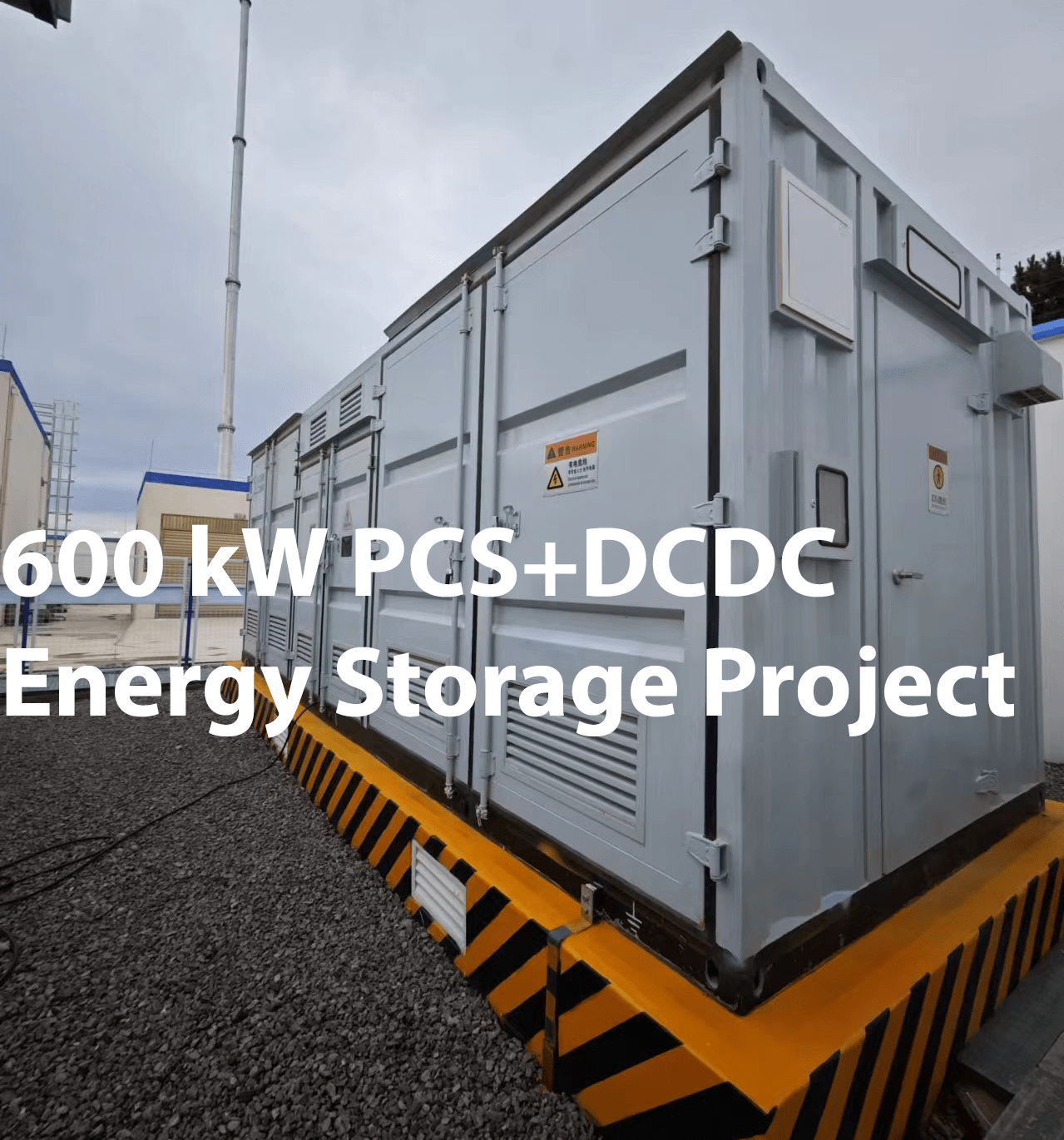
On-site cabinet photos

Two of the modules are installed below the capacitor cabinet, with a total compensation capacity of 1200A.
1.3 Test instructions
Test purpose: Master the harmonic data before and after the active power filter is put into operation, and prepare a harmonic control effect report
Test conditions: normal production under load
Voltage accuracy: 0.1%
Voltage range: 1000Vrms, 6000Vpeak
Current accuracy: 0.5%
Measurement meets IEC 61000-4-30 Class A standard
Safety level 600 V Cat IV/1000 V CAT III standard
2. Comparsion of data before and after filtering
Voltage harmonic distortion rate before equipment compensation


3.Conclusion
In the 400V side power distribution system of the transformer, before active harmonic filter compensation, the current distortion is serious. When the active harmonic filter is turned on, and the system current distortion rate is from 28.9% is reduced to 5.2%, and the system current and voltage waveforms are reduced from the previous severely distorted waveforms to basically close to sinusoidal waveforms; and the 5th harmonic current in the system is reduced from 389.3A to 19.6A, the compensation rate reaches 95%, and 2nd~13th and other harmonic currents were compensated by AHF/APF, the current content of each harmonic decreased, and the compensation effect was significant; after the reactive power compensation mode was turned on, the power factor of the incoming line cabinet was “1”.


