導入
現代の産業施設では, electrical energy efficiency is becoming increasingly important. CoEpower の上級電気エンジニアとして, I frequently encounter factories struggling with low power factor, excessive reactive power consumption, utility penalties, 電圧変動, and reduced system efficiency. These issues not only increase electricity costs but also affect the reliability and lifespan of critical equipment.
A well-designed reactive power compensation system can significantly improve power quality, エネルギー損失を減らす, increase system capacity, and lower utility charges. Whether you operate a manufacturing plant, mining facility, steel mill, water treatment station, or data center, understanding how to design an effective reactive power compensation system is essential.
This article provides a comprehensive guide to reactive power compensation system design, including load analysis, compensation equipment selection, 高調波の軽減, and modern solutions such as 静的 VAR ジェネレーター (SVGs).
Understanding Reactive Power in Industrial Facilities
Before designing a compensation system, it is important to understand what reactive power is.
Industrial loads such as:
- Induction motors
- トランスフォーマー
- 溶接機
- Compressors
- 可変周波数ドライブ (VFDS)
- HVAC equipment
require both active power (kW) and reactive power (左).
Active power performs useful work, while reactive power supports the magnetic fields required for equipment operation. Excessive reactive power demand leads to:
- 低い力率
- Higher current flow
- Increased transformer loading
- Higher cable losses
- Voltage drops
- Utility power factor penalties
The goal of reactive power compensation is to supply the required reactive power locally rather than drawing it from the utility grid.
ステップ 1: Analyze Factory Load Characteristics
The first step in designing a compensation system is conducting a detailed power quality survey.
Key parameters to measure include:
Total Active Power (kW)
Determine the factory’s average and peak active power demand.
Existing Power Factor
Measure:
- Average power factor
- Peak-load power factor
- Minimum power factor
Most utilities require a power factor above 0.90 または 0.95.
Reactive Power Demand (左)
Record reactive power consumption under different operating conditions.
Harmonic Distortion
Measure:
- THDi (Current Harmonics)
- THDv (電圧高調波)
This step is critical because harmonics greatly influence compensation equipment selection.
Load Variation
Evaluate whether loads are:
- Constant
- Intermittent
- Rapidly changing
Dynamic loads often require advanced compensation technologies.
ステップ 2: Define Compensation Objectives
Different factories have different goals.
Typical objectives include:
Improve Power Factor
例えば:
Current PF = 0.75
Target PF = 0.98
Reduce Utility Penalties
Many utilities charge penalties when power factor falls below contractual limits.
Release Transformer Capacity
Improving power factor reduces current demand and effectively increases available transformer capacity.
電圧を安定させます
Reactive power compensation helps maintain voltage levels throughout the plant.
Improve Equipment Performance
Better voltage regulation enhances motor efficiency and production reliability.
ステップ 3: Calculate Required Reactive Power Compensation
The required compensation capacity can be calculated using:
Qc = P × (tanφ1 − tanφ2)
どこ:
- Qc = Required compensation (左)
- P = Active power (kW)
- φ1 = Existing power factor angle
- φ2 = Target power factor angle
例
Factory Load:
- Active Power = 1000 kW
- Existing PF = 0.75
- Target PF = 0.98
tanφ1 = 0.882
tanφ2 = 0.203
Qc = 1000 × (0.882 − 0.203)
Qc = 679 左
A compensation system of approximately 680 kVAR is required.
実際に, engineers typically add a design margin of 10%–20%.
ステップ 4: Select the Appropriate Compensation Technology
Several technologies are available for reactive power compensation.
Fixed Capacitor Banks
Suitable for:
- Constant loads
- Stable operating conditions
利点:
- Low cost
- Simple installation
Limitations:
- No automatic adjustment
- Risk of overcompensation
Automatic Power Factor Correction (APFC) コンデンサバンク
Suitable for:
- Variable industrial loads
利点:
- Automatic switching
- Better power factor control
- Cost-effective
アプリケーション:
- 製造工場
- 水処理施設
- 商業ビル
サイリスタはコンデンサを切り替えました (TSC)
Suitable for:
- 急速に変化する負荷
利点:
- Rapid response
- No switching transients
アプリケーション:
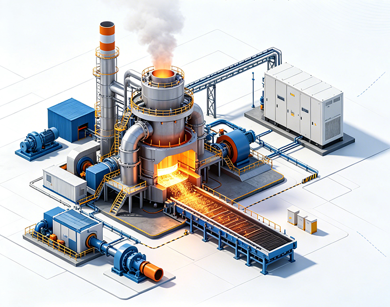
- Welding plants
- Steel mills
- Rolling mills
静的varジェネレーター (SVG)
SVG technology represents the most advanced reactive power compensation solution available today.
利点:
素早い応答
Response time typically less than 10 ミリ秒.
Precise Compensation
Continuously adjusts output based on system requirements.
Capacitive and Inductive Compensation
Unlike traditional capacitors, SVG can both generate and absorb reactive power.
Excellent Performance Under Low Loads
Maintains high compensation accuracy across all operating conditions.
Harmonic Suppression Capability
Many SVG systems provide limited harmonic filtering functions.
アプリケーション:
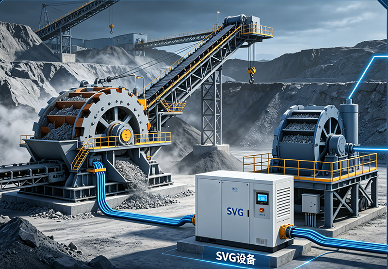
- Mining industry
- データセンター
- Semiconductor plants
- 再生可能エネルギーシステム
- 工業用製造施設
コエパワーで, SVG solutions are increasingly becoming the preferred choice for modern industrial power factor correction projects.
ステップ 5: Consider Harmonic Conditions
Many factories today use:
- 可変周波数ドライブ
- UPSシステム
- 整流器
- Servo drives
These devices generate harmonics that can damage capacitor banks.
Potential problems include:
- Capacitor overheating
- Resonance
- Equipment failure
- 変圧器の過熱
したがって, harmonic analysis is essential.
When Harmonics Are Present
Detuned Capacitor Banks
Reactors are added to capacitor banks to avoid resonance.
Typical tuning frequencies:
- 189 Hz
- 210 Hz
Widely used in industrial applications.
アクティブハーモニックフィルター (AHF)
For facilities with significant harmonic distortion, Active Harmonic Filters are often recommended.
利点:
- Dynamic harmonic elimination
- 反応性電力補償
- Improved power quality
SVG + AHF Hybrid Solutions
Modern factories often deploy:
- SVG for reactive power compensation
- 高調波フィルタリング用の AHF
This combination provides comprehensive power quality improvement.
ステップ 6: Determine Compensation Installation Location
Compensation can be installed at different levels.
Centralized Compensation
Installed at the main distribution board.
利点:
- Lower investment cost
- Easier maintenance
に最適です:
- Small to medium factories
Group Compensation
Installed at sub-distribution panels.
利点:
- Better voltage support
- Reduced feeder losses
に最適です:
- Large manufacturing facilities
Individual Compensation
Installed directly at motors or equipment.
利点:
- Maximum efficiency
に最適です:
- Large continuously operating motors
ステップ 7: Design Monitoring and Control Systems
A modern compensation system should include:
Power Quality Monitoring
Monitor:
- 力率
- 電圧
- Current
- ハーモニクス
- 無効電力
Communication Interfaces
Common protocols include:
- Modbus RTU
- Modbus TCP
- イーサネット
リモート監視
Factory operators can monitor system performance in real time through SCADA or Energy Management Systems (EMS).
ステップ 8: Evaluate Future Expansion Requirements
One common design mistake is sizing compensation systems only for current loads.
Factories often expand production capacity.
Engineers should:
- Reserve panel space
- Reserve communication capacity
- Design for 20%–30% future load growth
This avoids costly future upgrades.
Common Design Mistakes to Avoid
Overcompensation
Excessive compensation can create leading power factor issues.
Ignoring Harmonics
Capacitors installed without harmonic studies often fail prematurely.
Undersized Compensation
Insufficient compensation fails to achieve target power factor.
Choosing Traditional Capacitors for Dynamic Loads
Rapid load fluctuations require SVG or TSC technology.
Lack of Monitoring
Without monitoring, performance degradation may go unnoticed.
Why SVG Technology Is Becoming the Preferred Solution
The industrial power environment is changing rapidly.
Factories increasingly use:
- Automation systems
- VFD駆動モーター
- ロボット工学
- 再生可能エネルギーの統合
Traditional capacitor banks often struggle to meet modern compensation requirements.
Static Var Generators offer:
- Instantaneous response
- 高い補正精度
- No overcompensation
- Bidirectional reactive power control
- Compatibility with harmonic-rich environments
結果として, SVG technology has become the preferred solution for many industrial power quality projects worldwide.
結論
Designing an effective reactive power compensation system requires a thorough understanding of factory load characteristics, power factor requirements, harmonic conditions, and future expansion plans.
A properly designed system can:
- Reduce electricity costs
- Eliminate power factor penalties
- Improve voltage stability
- Increase transformer capacity
- Extend equipment lifespan
- Enhance overall power quality
While traditional capacitor banks remain suitable for certain applications, modern industrial facilities increasingly benefit from advanced solutions such as Static Var Generators (SVGs) and Active Harmonic Filters (AHFS).
コエパワーで, we specialize in providing customized reactive power compensation solutions tailored to the unique requirements of industrial, 採掘, コマーシャル, and utility applications. Through professional power quality analysis and advanced compensation technologies, we help customers achieve higher efficiency, lower operating costs, and more reliable electrical systems.
キーワードタグ
Reactive Power Compensation System, 力率補正, Factory Reactive Power Compensation, 静的varジェネレーター, SVG Power Factor Correction, 産業用電力の品質, Automatic Capacitor Bank, アクティブハーモニックフィルター, Reactive Power Compensation Design, 力率の改善, 高調波緩和, Industrial Energy Saving, Electrical Distribution System, CoEpower SVG Solution, Factory Energy Efficiency, サプライヤー, メーカー, 工場, 会社, 中国, 卸売, 買う, 価格, 引用, バルク, 販売のため, 企業, ストック, 料金.