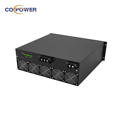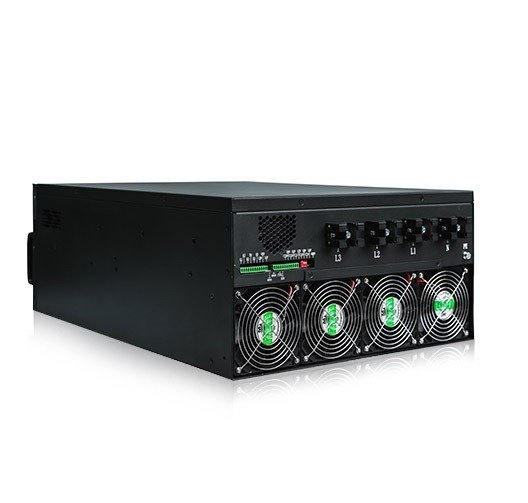


SVG Static Var Generator is a product aimed at Power Factor Correction and Harmonic Filtering, along with a Three-phase balancing Function. Benefiting from inverter technology, the SVG Static Var Generator PFC series’ compensation is stepless, which means SVG output shall match the system reactive power, with no over-compensation or under-compensation. For a single module, SVG capacity ranges from 30kVA to 100kVA. For the Abinet system, it’s an unlimited parallel design. When the load is generating inductive or capacitive current, it makes the load current lag or lead the voltage. SVG detects the phase angle difference and generates a leading or lagging current into the grid, making the phase angle of current almost the same as that of voltage on the transformer side, which means the fundamental power factor is unity.
 |
 |
| Cabinet capacity | 30-500kvar cabinet |
| Rated Voltage(V) | 220V/400V/480V/690V |
| Rated Frequency (Hz) | 50HZ/60HZ |
| Network Configuration | 1P2W/3P4W/3P3W |
| CT Ratio | 100:5~6000:5 |
| Topology Design | 3 Level |
| Power Factor Correction | PF=0.99 |
| Full response time | ≤10ms |
| IGBT Frequency | 20KHz |
| Communication Interface | RS485, Ethernet |
| Communication Protocol | Modbus protocol |
| Protection Class | IP 20 |
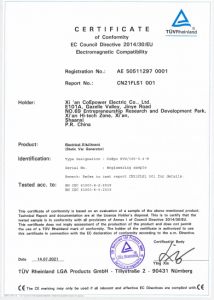
| Certificate | TUV CE/AS/URL |
| Noise Level | <60db |
In modern electrical systems, many types of industrial equipment, such as motors, inverters, and welding machines, draw inductive or capacitive current. This causes the current to lag behind or lead ahead of the voltage, resulting in a non-unity power factor and poor power quality.
The CoEpower Static Var Generator is designed to solve this issue dynamically and precisely.
(1). Real-Time Detection
The CoEpower SVG continuously monitors the electrical load in real time by detecting the phase angle difference between the current and voltage. This phase angle difference indicates whether the system is experiencing:
-Inductive load (current lags voltage)
-Capacitive load (current leads voltage)
(2). Instantaneous Compensation
Once the CoEpower SVG detects a phase mismatch, it uses its built-in fast-switching power electronic components (e.g., IGBTs) to generate a compensating current:
-If the load is inductive, it generates a leading (capacitive) current.
-If the load is capacitive, it generates a lagging (inductive) current.
This compensating current is injected into the grid or system at the point of common coupling.
(3). Achieving Unity Power Factor
The goal of the CoEpower SVG is to make the current waveform align closely with the voltage waveform at the transformer or system input. When the current and voltage are in phase, the fundamental power factor is corrected to nearly 1.0, which means:
-Maximum efficiency in power delivery
-Minimal reactive power flow
-Reduced energy loss and equipment stress
(4). Intelligent & Adaptive Operation
Unlike traditional capacitor banks that switch in fixed steps, the CoEpower SVG provides smooth, stepless compensation with millisecond response times. It dynamically adapts to:
-Rapid load changes
-Fluctuating power factor
-Complex harmonic-rich environments
The CoEpower Static Var Generator works by detecting and correcting phase angle imbalances between current and voltage in real time. By injecting an exact amount of reactive power—either leading or lagging—it ensures that your system operates with high efficiency, minimal losses, and maximum power quality.
IGBT DSP control system makes the reactive power compensation from mechanical compensation evolve to intelligent power electronic stability compensation. Whatever the load current changes, SVG can always output the corresponding compensation current to realize the perfect combination. Always keep the power factor as 0.99. Running well in a severe environment like high THDU/high ambient temperature/high amplitude.
 |
 |
 |
 |
Note: Always consult the manufacturer’s manual and hire a licensed electrician or engineer for actual installation.
(1) Site Assessment & Load Analysis
Measure your system’s power factor, load profile, and reactive power demand using a power quality analyzer.
Identify where the SVG should be placed (main distribution panel, sub-panel, or near heavy loads).
Choose a properly sized SVG unit based on reactive power (kVAR) requirements.
(2) Unpacking & Inspection
Carefully unpack the SVG and check for physical damage during transport.
Verify that the voltage rating, current rating, and frequency match your system.
(3)Physical Installation
Mount the SVG in a clean, dry, and well-ventilated location (avoid high temperatures or dusty areas).
Ensure enough space for heat dissipation and future maintenance.
Secure the SVG using floor or wall mounts (depending on the model).
(4) Electrical Connections
Power Connection: Connect the SVG input terminals to the busbar or main distribution line using appropriately rated cables.
CT Connection (Current Transformers):
-Connect the CTs to measure load current.
-Install CTs in the correct phase sequence and direction.
-Typically placed on the incoming lines before the load.
Control Wiring: Connect the CT signals and control communication (RS485, Modbus, etc.) to the SVG controller.
(5) Commissioning & Configuration
Power on the SVG.
Configure the following settings using the built-in display or external software:
-System voltage and current ratings
-CT ratio
-Target power factor
-Communication parameters
Perform a function test to ensure the SVG is injecting/absorbing reactive power properly.
(6) Final Checks and Monitoring
Monitor the SVG’s performance for a few hours or days to ensure:
-Power factor is improving (near 1.0)
-No abnormal alarms or overheating
-Voltage and current are within safe limits
Set up remote monitoring, if available.
(7) Safety Reminders
Always disconnect power before making any electrical connections.
Use PPE (personal protective equipment) and follow lockout-tagout (LOTO) procedures.
Only qualified personnel should perform the installation.

Hot Tags: SVG static var generator PFC series, China, suppliers, manufacturers, factory, customized, wholesale, price, hot sale, high quality, price list, free sample, 110V SVG Reactive Power Compensator, Flexible Configuration Parallel SVG Panel, 220V SVG Reactive Energy Compensation, SVG Static Var Generator, Power Factor Correction, Harmonic Filtering, Static Var Generator PFC series, 30kvar SVG, 100kvar SVG, 30-500kvar SVGcabinet, How Static Var Generator works.